





How Does Vibration Affect Dental Milling Accuracy?
 Oct 20, 2026|

How Does Vibration Affect Dental Milling Accuracy?
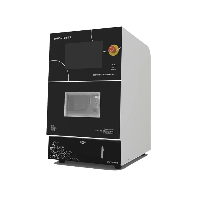
A dental milling machine can complete a job without displaying an error, yet the milled surface may show uneven marks, fine ridges or an unexpected loss of detail. In some cases, the machine sounds normal when the spindle is running without a cutting load but becomes noticeably louder once the bur enters the material.
These changes may be related to vibration.
In machining, vibration refers to repeated movement of the tool, workpiece or machine structure around its operating position. Some movement is unavoidable in a mechanical system. The concern is whether the vibration becomes large enough, or occurs under conditions that make it interfere with the cutting process.
For dental laboratories, this matters because restorations contain small features and curved surfaces that leave relatively little room for machining errors. Vibration may affect surface texture, dimensional consistency, tool life and the amount of finishing work required after milling.
However, vibration does not always indicate a defective machine. It can originate from the cutting process, an unsuitable tool, an unstable fixture, a loose mechanical connection or an interaction between spindle speed and the machine's natural vibration characteristics.
A useful investigation begins by identifying when the vibration occurs, what it sounds or looks like, and whether it changes with the machining conditions.
This article examines these issues from a manufacturing perspective, with practical examples that dental laboratories and distributors can use when evaluating equipment or investigating machining problems.
1. What Does Vibration Mean in Dental Milling?
During milling, the cutting tool and the material exert forces on each other. These forces change as the tool rotates, enters the material, removes chips and moves along the programmed path.
The machine structure, spindle, tool holder and cutting tool all have some degree of flexibility. When cutting forces act on this system, the components may move slightly away from their intended positions.
If this movement repeats or develops into an unstable oscillation, it can change the way the cutting edge meets the material.
A 2025 review of precision and micromilling research discusses the relationship between cutting forces, tool displacement and vibration. It explains that these effects can influence dimensional accuracy, surface roughness, surface waviness and tool wear. Although the review is not limited to dental milling, the mechanical principles are relevant to the small tools and fine features found in dental CAD/CAM work.
For practical purposes, vibration can be divided into two broad conditions.
Low-level vibration: Small movements occur during normal operation but do not necessarily produce a noticeable defect or exceed the machine's specified acceptance limits.
Problematic vibration: Movement becomes sufficiently large or unstable to affect cutting quality, increase tool loading or produce visible marks on the machined surface.
The key factor is not simply whether vibration exists. It is how that vibration interacts with the cutting process.
A machine that feels slightly different when the spindle is running without cutting may not have the same problem as one that develops a strong oscillation only when machining a particular material or feature. The two situations call for different investigations.
2. Three Types of Vibration Worth Understanding
For troubleshooting purposes, vibration can be grouped into three broad categories: forced vibration, free vibration and self-excited vibration. These categories help explain why a machine may behave differently under different operating conditions.
Forced vibration
Forced vibration occurs when an external or periodic force causes a system to vibrate.
Possible sources include an unbalanced rotating component, periodic cutting forces, a vibrating auxiliary component or a disturbance transmitted through the machine's mounting structure.
For example, an imbalance in a rotating assembly can generate a periodic force. As rotational speed increases, the frequency of that force also increases. The machine may respond more strongly at certain speeds than at others, depending on its mechanical characteristics.
Free vibration
Free vibration occurs when a system is displaced and then allowed to respond according to its own natural characteristics.
A simple example is a spring that moves after being pushed and then released. A milling machine behaves in a more complicated way, but the underlying principle is similar.
When a cutting tool enters the material, the resulting force can excite a structural response. The vibration may continue briefly even after the original disturbance changes.
Self-excited vibration
Self-excited vibration is more complicated because the cutting process itself can sustain or amplify the oscillation.
In milling, this behavior is often associated with chatter. Movement of the tool changes the cutting conditions, which changes the cutting force. The altered force can then increase the movement again.
Under an unstable combination of machine stiffness, tool geometry and cutting conditions, the oscillation may grow rather than settle down.
Chatter can produce repeating patterns on a machined surface and may increase tool wear or cause cutting-edge damage.
The distinction matters during troubleshooting. A loose component may require mechanical correction, while chatter may call for an investigation of the tool setup and machining parameters as well.
3. How Does Vibration Change the Milled Surface?
One of the most direct effects of vibration is a change in surface texture.
Under stable conditions, the cutting edges follow a predictable path and leave a relatively consistent surface pattern. If the tool repeatedly moves away from its intended path and returns, the resulting surface may contain additional ridges, waviness or irregular marks.
The appearance depends on the vibration frequency, its amplitude, the direction of movement and the toolpath.
A 2013 study published in the International Journal of Machine Tools and Manufacture investigated spindle vibration during ultra-precision raster milling. Its theoretical and experimental findings showed that spindle vibration could produce uneven surface scallops, including ribbon-like stripes and irregular patterns resembling those associated with runout. The study used a specialized ultra-precision machining system rather than a dental milling machine, so it helps explain the mechanism but cannot predict the surface quality of a particular dental restoration.
For a dental laboratory, several surface patterns may justify further investigation:
Repeated parallel lines that were not present in previous jobs.
Fine ridges appearing at regular intervals.
Localized roughness that becomes more obvious in one machining direction.
A surface that looks acceptable across broad areas but becomes irregular around narrow or curved features.
These observations are clues rather than definitive diagnoses. Tool geometry, CAM strategy, material behavior and tool condition can also produce surface marks.
Comparing the affected restoration with a previous part made from the same material and using the same settings can help establish whether the pattern has changed. Record the differences before adjusting several machine parameters at once.
Why finishing can reveal a problem that was easy to miss
A restoration may look acceptable under ordinary lighting but show more obvious irregularities under magnification or directional lighting.
For example, a technician may notice repeated fine marks on an internal surface while checking a crown under a microscope. If the same pattern appears on several consecutive restorations, the laboratory has a reason to examine the machining process rather than treating each surface as an isolated finishing issue.
The next step is to determine whether the marks correspond to the toolpath, a particular cutting direction or a change in machine vibration.
A surface defect alone cannot identify the source. Its location and pattern provide more useful information when considered alongside the machining conditions.
4. Can Vibration Change Dimensional Accuracy?
Yes. Vibration can affect dimensions when it causes the cutting edge to move away from its intended path.
Consider a tool cutting an internal curved surface. If the tool deflects outward under a changing cutting force, it may remove a different amount of material than expected. As the force changes, the tool may move back toward its previous position.
The resulting surface can contain local dimensional deviations even though the machine has completed the programmed path.
The effect is not necessarily equal to the measured vibration amplitude. The relationship depends on the direction of movement, tool geometry, contact between the cutting edge and the material, and the dynamic response of the machine.
This distinction matters when interpreting measurements. A vibration sensor may record movement at the machine housing, but that reading does not directly indicate how far the cutting edge has moved relative to the workpiece.
For example, a sensor attached to the frame measures the local motion of that frame. It does not automatically measure tool-tip displacement.
Vibration measurements and finished-part inspections therefore serve different purposes. Both can be useful, but they answer different questions. A sensor helps characterize machine movement at a particular location, while inspection of the milled part shows whether the machining process has produced an unacceptable result.
5. Why Small Tools and Long Tool Extensions Are More Sensitive
Tool geometry affects how a cutting tool responds to force.
A short, thick tool generally has greater bending stiffness than a longer, more slender tool made from the same material with a comparable cross-section. As the unsupported length increases, the tool becomes more susceptible to bending, and its dynamic response can change substantially.
This is relevant when a dental restoration contains a deep or narrow feature that requires a tool with greater reach. The tool may need to extend farther from the holder to access the area. That additional length can make it more sensitive to cutting forces and vibration.
A 2013 experimental study examined the milling of hardened steel using tools with different diameters and overhang lengths. The researchers measured tool wear, cutting forces, surface roughness and the dynamic response of the tool. Their findings indicated that machining stability depended partly on the relationship between the tool's vibration characteristics and the frequency of the cutting process. The study also showed that tool wear and surface roughness did not always change in the same way, illustrating why vibration-related effects cannot always be evaluated through a single measurement.
Although the workpiece material was hardened steel, the mechanical principle is relevant to dental machining: a tool's performance depends on its stiffness and dynamic behavior, not just its nominal diameter.
For a laboratory, a defect that occurs only in deep internal features may require a different investigation from one that appears across every milled surface.
The technician should record which tool was used, how far it extended from the holder and where the surface defect appeared. These details can help narrow down the possible causes.
6. The Relationship Between Vibration, Cutting Forces and Tool Wear
Vibration and tool wear can influence each other.
A worn cutting edge may require greater force to remove material. Uneven wear across the cutting edges can also make the cutting forces less uniform. These changes may increase the vibration response of the machining system.
Conversely, excessive vibration can produce fluctuating loads on the cutting edge, increasing the risk of localized damage under unfavorable conditions.
A 2018 study by Xu and colleagues investigated the relationships between cutting parameters, tool wear, cutting forces and vibration during stainless-steel milling. Under the conditions tested, the researchers found that tool wear and milling depth had significant effects on cutting forces and vibration. They also discussed how vibration can produce chatter marks and reduce surface quality.
The material and machine setup in that study differed from those used in dental CAD/CAM milling, so its numerical results should not be transferred directly to zirconia or other dental materials.
The broader relationship helps explain a common diagnostic problem: when surface quality deteriorates, vibration may be both a symptom of an existing problem and a factor that contributes to further deterioration.
A laboratory should avoid assuming that the first visible change identifies the original cause.
If a tool is already worn, reducing the feed rate might make the sound less noticeable without correcting the tool's condition. If the machine has a loose mechanical connection, replacing the bur may temporarily improve the result while leaving the underlying problem unresolved.
A more useful approach is to consider the symptoms together and test one likely cause at a time.
7. Why Can a Machine Vibrate at One Spindle Speed but Not Another?
A machine's vibration does not always increase steadily as spindle speed rises. In some cases, a particular speed produces a much stronger response than a slightly lower or higher speed.
One possible explanation is resonance.
Every mechanical structure has natural frequencies at which it responds more strongly to certain disturbances. When the frequency of an external force approaches one of these frequencies, the resulting vibration may become more pronounced.
A milling machine is a complex structure, so it does not have just one natural frequency. The spindle assembly, tool, holder, frame and mounting structure can all have different dynamic characteristics.
The cutting process also generates periodic forces. If these forces interact unfavorably with the machine's dynamic response, vibration may become more noticeable.
A numerical example
Consider a hypothetical milling operation at 30,000 rpm.
The rotational frequency is:
[
30{,}000 \div 60 = 500 \text{ revolutions per second}
]
The rotational frequency is therefore 500 Hz.
At 36,000 rpm, the rotational frequency becomes 600 Hz.
These figures describe rotational frequency, not the complete vibration spectrum. The vibration signal may also contain harmonics, cutting-edge passing frequencies and frequencies associated with other mechanical components.
If a technician finds that vibration rises sharply around one operating speed, it may be worth examining the frequency content of the signal and checking whether a machine or tool mode is being excited.
Simply avoiding that speed does not necessarily resolve the underlying problem. A speed adjustment may reduce vibration during a particular operation, but unusual vibration or a change in machine performance still warrants investigation.
For manufacturers, speed-dependent testing can reveal information that a single no-load measurement may miss.
8. How Can a Laboratory Tell Whether Vibration Comes from the Machine or the Cutting Process?
The first step is to observe when the vibration occurs.
A machine that vibrates continuously, even without cutting, presents a different diagnostic situation from one that becomes unstable only during a particular operation.
The following comparison can help organize the investigation.
| Observation | Possible areas to investigate |
|---|---|
| Vibration occurs with no cutting load | Rotating components, spindle condition, imbalance, mounting or other machine components |
| Vibration appears only when cutting | Cutting forces, tool condition, tool extension, machining parameters or workpiece support |
| Vibration occurs only at certain speeds | Speed-dependent dynamic response, imbalance or resonance |
| Vibration appears after a tool change | Tool condition, holder, installation or tool geometry |
| Vibration occurs mainly in deep features | Tool extension, tool stiffness, access geometry and cutting strategy |
| Vibration begins after maintenance | Assembly, mounting, connections or component installation |
These are possible investigation paths, not diagnoses. Different causes can produce similar symptoms.
A useful test is to compare the machine's behavior under repeatable conditions. If the manufacturer provides an approved no-load test, follow that procedure and record the operating speed and measurement location. Do not run an improvised test at a speed or configuration that the manufacturer has not approved.
If the machine is stable without cutting but vibrates during a particular milling operation, the technician should document the material, tool, tool extension, spindle speed, feed settings and location of the affected feature.
This record makes it easier to reproduce the problem and discuss it with the machine supplier.
9. A Practical Example: Vibration Appears Only on Deep Internal Features
Consider a hypothetical dental laboratory that notices rough surfaces in deep internal areas of several restorations.
The outer surfaces remain acceptable, and the machine does not display an alarm. The problem appears mainly when a long-reach tool is used.
Instead of changing the entire CAM profile, the technician can compare two controlled test conditions.
Test A: Use the original tool and machining parameters.
Test B: Use a suitable tool with a shorter unsupported length, where the geometry allows it, while keeping the other relevant conditions unchanged.
If the vibration-related symptoms become less pronounced in Test B, tool stiffness and overhang become plausible contributors. The result would not prove that the machine has no mechanical issues, but it would help narrow the investigation.
The technician can then examine the tool, holder, machining strategy and machine condition in more detail.
The principle is straightforward: a useful troubleshooting test changes one relevant variable at a time.
Changing the tool, spindle speed, feed rate and CAM strategy simultaneously might improve the surface, but it would not show which change made the difference.
10. How Should Vibration Be Measured?
Hearing and touch can help identify a change in machine behavior, but they are not reliable substitutes for measurement.
A machine may produce high-frequency vibration that is difficult to feel by hand. Conversely, a noticeable sound may come from a component that does not directly determine the movement of the cutting edge.
For engineering investigations, common measurement options include:
Accelerometers: Measure vibration acceleration at the location where the sensor is installed.
Displacement sensors: Measure movement relative to a reference, provided the sensor and setup are suitable.
Vibration analyzers: Help examine vibration amplitude and frequency content.
Acoustic measurements: Record sound pressure or sound patterns. These can provide supporting information but do not directly measure tool-tip movement.
The sensor location matters
A reading taken on the outer machine cover may be useful for monitoring changes in the overall machine response. It cannot automatically be treated as the vibration amplitude at the spindle or cutting edge.
For meaningful comparisons, the sensor position, machine state, spindle speed, measurement units and test conditions should be recorded.
Why frequency matters as much as amplitude
Suppose two tests show similar overall vibration amplitudes.
One signal is dominated by a stable rotational component, while the other contains intermittent peaks and a broader range of frequencies. The signals may indicate different mechanical conditions even if a single overall value looks similar.
A frequency spectrum can help identify whether the vibration is associated with rotational speed, another periodic component or a more complex cutting instability.
Identifying the source usually requires comparison with known operating conditions and an appropriate diagnostic procedure. A frequency peak alone does not prove that a particular component has failed.
11. What Can a Manufacturer Do to Reduce Unwanted Vibration?
Vibration control involves the complete mechanical system rather than one specification.
During machine development and quality control, a manufacturer may investigate several areas.
Structural stiffness
The frame and mechanical supports must resist the forces generated during machining. Excessive structural flexibility can increase movement under load.
Spindle and rotating assembly
The spindle assembly should be checked according to the manufacturer's inspection procedure. Abnormal vibration, sound or temperature changes should be investigated rather than dismissed simply because the spindle still reaches its rated speed.
Tool-holder interface
The holder must retain the tool correctly during operation. The tool, holder and spindle form a connected system, so testing only one component may not explain the behavior of the complete assembly.
Mechanical connections and mounting
Loose connections, unsuitable mounting conditions or changes in the supporting structure can affect vibration transmission and machine behavior.
Operating conditions
Spindle speed, feed rate, tool geometry and cutting engagement should be considered together. A machining condition that works well with one tool or material may not produce the same result with another.
A manufacturer cannot reasonably claim that vibration can be eliminated completely. The practical goals are to understand the machine's normal behavior, define acceptable operating conditions and provide a repeatable procedure for investigating abnormal changes.
12. What Should Buyers Ask Before Purchasing a Dental Milling Machine?
For overseas distributors and laboratories, vibration is worth discussing before a machine is installed at the customer's site.
The following questions can help distinguish a general marketing claim from useful engineering information.
How is vibration checked before shipment?
Ask whether the manufacturer has a defined test procedure, where measurements are taken and whether the results are recorded.
Is the machine tested only without cutting?
A no-load test and a machining test provide different information. Ask which tests are performed and what each one is intended to verify.
Can the manufacturer explain the test conditions?
A vibration figure is meaningful only when the measurement location, operating speed, units and test conditions are known.
What happens if vibration increases during normal use?
The manufacturer should be able to explain the initial checks, the information the customer should record and when technical service is required.
Does the service team have a repeatable diagnostic procedure?
A useful procedure should help distinguish between a tool-related problem, a machining-condition problem and a possible mechanical fault.
Can the manufacturer support the distributor remotely?
For overseas customers, clear troubleshooting instructions and access to technical support can be as important as the initial inspection result.
Buyers do not need to become vibration engineers to ask these questions. The answers help establish whether the manufacturer understands how the machine behaves in practical use.
13. A Simple Vibration Record for Dental Laboratories
Laboratories that encounter intermittent surface problems can benefit from keeping a basic record.
| Record item | What to note |
|---|---|
| Date and machine ID | Identify when and where the issue occurred |
| Material | Record the material and product batch where relevant |
| Tool | Record the tool type and usage history |
| Machining operation | Identify the affected restoration or feature |
| Spindle speed | Record the programmed speed |
| Observation | Describe the sound, visible marks or measured vibration |
| Operating condition | Note whether the issue occurred without cutting or during milling |
| Action taken | Record the single variable changed during each test |
| Result | State whether the symptom improved, remained unchanged or became worse |
This record can help reveal whether a problem is associated with a particular tool, material, machining operation or operating speed.
It is also useful when the laboratory contacts the distributor. Instead of reporting only that "the machine is vibrating," the customer can provide a repeatable description of the problem.
Clear records make remote technical support more productive and reduce the risk of unnecessary parameter changes.
Conclusion
Vibration affects dental milling when movement within the machine-tool-workpiece system changes the way the cutting edge removes material. Depending on its source and severity, it can contribute to surface irregularities, dimensional deviations, tool wear and unstable machining.
Research in precision milling shows that the relationship between vibration, cutting forces, tool geometry and surface generation is complex. The effect depends on the complete machining setup, not simply on whether a machine produces an audible sound.
For dental laboratories, the first step is to identify when the vibration occurs and document the operating conditions. For distributors, the priority is to understand the manufacturer's testing and troubleshooting procedures.
A quiet machine is not automatically an accurate machine, and a machine that produces measurable vibration is not necessarily defective.
The relevant question is whether the vibration remains within the manufacturer's defined limits and whether the machine maintains consistent machining performance under its intended operating conditions.
For a dental milling machine manufacturer, that is a more meaningful engineering question than promising that the machine has no vibration at all.