





What Is Spindle Runout and Why Does It Matter in Dental Milling?
 Oct 12, 2026|
What Is Spindle Runout and Why Does It Matter in Dental Milling?
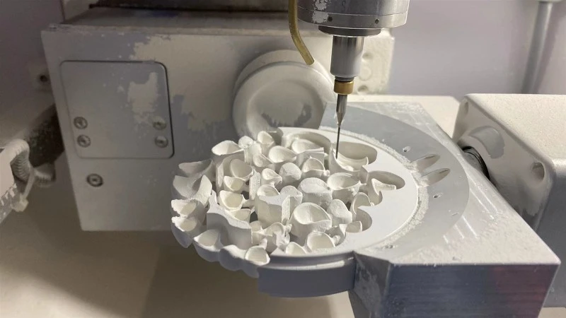
When comparing dental milling machines, buyers often focus on spindle speed, tool capacity, machining time, and the accuracy figures listed on the specification sheet. One technical detail that receives less attention is spindle runout.
At first, it may not seem like a major concern. The spindle rotates, the bur cuts the material, and the machine follows the programmed toolpath. If the spindle reaches 60,000 rpm, it is easy to assume that everything is working as intended.
Rotational speed, however, is not the same as rotational accuracy.
A spindle can reach its rated speed while the tool still deviates from its intended rotational axis. When this happens, the effective cutting path may differ from the programmed path. Some parts of the cutting edge may remove more material than others, affecting surface quality, tool wear, and dimensional accuracy.
In a dental laboratory producing crowns, bridges, and other restorations, these differences may become noticeable in narrow internal areas and fine anatomical details. Distributors also benefit from understanding spindle runout when comparing machines or helping customers investigate machining problems.
This article explains what spindle runout means, how it is measured, why small dental milling burs are sensitive to it, and what buyers should ask before purchasing a machine.
1. What Is Spindle Runout?
Spindle runout describes the deviation observed when a rotating spindle surface or a tool mounted in the spindle does not follow a perfectly consistent rotational path.
Imagine mounting a straight milling bur in a spindle and observing the cutting tip while the spindle rotates. If the tip moves slightly from side to side instead of following a consistent circular path, that movement indicates runout.
The term is sometimes used loosely to describe several different conditions. In precision machining, however, it is useful to distinguish between the spindle's own geometric condition, the tool-holder interface, and the runout measured at the installed cutting tool.
These measurements are related, but they are not interchangeable.
For example, a spindle may show relatively low runout at its taper, while a contaminated collet or a tool with a dimensional defect produces greater runout at the cutting tip.
A measurement taken at one location may therefore tell only part of the story.
Radial runout and axial runout
Two terms are particularly useful when discussing spindle performance.
Radial runout refers to variation in the radial position of a rotating surface. When a cylindrical tool is mounted in the spindle, radial runout is commonly observed as movement from side to side.
Axial runout refers to variation along the spindle axis, often measured at a rotating face or end surface.
In dental milling, radial runout at the cutting tool is particularly relevant because it can change the effective radius of the cutting path. Axial error may also affect cutting conditions, depending on the tool geometry and the surface being machined.
A technician should not treat all runout measurements as if they describe the same thing.
2. What Does TIR Mean?
Manufacturers and technicians often use the abbreviation TIR when discussing spindle runout. TIR stands for total indicator reading, also commonly called total indicated runout.
A dial indicator or suitable electronic measuring instrument is positioned against the test surface. The spindle is rotated slowly, and the highest and lowest readings are recorded.
TIR is the difference between those readings.
For example, suppose a dial indicator gives the following readings during one complete rotation:
Highest reading: +0.006 mm
Lowest reading: −0.004 mm
The measured TIR is:
0.006 − (−0.004) = 0.010 mm
The result is 10 μm TIR.
This is a measurement example, not a performance claim for any particular dental milling machine.
TIR is not automatically the same as the actual radial displacement of the spindle axis. The relationship depends on the geometry of the measured surface, the type of error, and the measurement setup.
For a buyer, the useful question is not simply whether the manufacturer can provide a runout figure. It is whether the manufacturer can explain where, how, and under what conditions the measurement was taken.
3. Why Does Runout Matter in Dental Milling?
The main concern is that the cutting edge may not remove material in the way expected by the programmed toolpath.
Consider a milling bur with a nominal diameter of 1.0 mm. If runout changes the effective cutting envelope, the tool may remove more material than expected in certain areas.
The actual result depends on the tool geometry, runout direction, cutting conditions, and machining strategy. It would be incorrect to assume that every measured runout value translates directly into an equal dimensional error in the finished restoration.
The basic relationship is straightforward: when the cutting edge does not follow the expected rotational path, the material-removal process changes.
Research published in the International Journal of Machine Tools and Manufacture investigated the effects of cutter runout on surface topography, surface-location error, and machining stability. The researchers found that uneven cutting-edge positions can produce unequal chip loads, influencing cutting forces, surface finish, and the risk of premature cutting-edge failure.
The study used a precision milling machine with reported positioning repeatability of 0.1 μm and spindle error motion of 0.02 μm. These figures describe the experimental equipment; they are not recommended runout limits for dental milling machines.
The findings help explain why good machine-positioning performance does not eliminate every possible source of error at the rotating cutting tool.
For a dental laboratory, possible consequences include:
uneven cutting marks;
changes in the dimensions of milled features;
rougher surfaces;
increased stress on small burs;
and inconsistent machining results.
None of these symptoms proves that spindle runout is excessive. They are reasons to investigate runout alongside other possible causes.
4. Why Are Small Dental Milling Burs Particularly Sensitive?
Dental restorations contain narrow spaces, small grooves, and curved internal surfaces. These features often require small-diameter cutting tools.
A small tool has less material supporting its cutting edge than a larger tool. Its performance can therefore be more sensitive to tool deflection, mounting errors, and runout.
A review of precision micro-milling published in Advances in Manufacturing explains that tool-setting errors, tool-holder errors, and spindle errors can combine to produce significant runout at the cutting edge. It also discusses how runout can influence cutting forces, surface integrity, and tool wear in micro-milling applications.
The review describes micro-milling tools as having cutting-edge diameters below 1,000 μm, although dental milling also uses larger tools. Its findings help explain why very small tools require careful control, but they should not be interpreted as a dental-specific acceptance standard.
A simple numerical example
Suppose a laboratory uses a 0.6 mm bur to machine a narrow internal feature.
If the measured TIR at the cutting region is 0.010 mm, that value is equivalent to approximately 1.67% of the nominal tool diameter.
If the TIR is 0.020 mm, the proportion rises to approximately 3.33%.
| Nominal bur diameter | Measured TIR | TIR as a proportion of diameter |
|---|---|---|
| 0.6 mm | 0.010 mm | 1.67% |
| 0.6 mm | 0.020 mm | 3.33% |
| 1.0 mm | 0.010 mm | 1.00% |
| 1.0 mm | 0.020 mm | 2.00% |
These percentages are simple comparisons, not predictions of the finished restoration's dimensional error. TIR does not translate directly into an equivalent error in the machined surface.
The comparison does, however, help explain why a runout figure that looks small on a specification sheet may deserve closer attention when very small tools are used.
5. Does Higher Spindle Speed Mean Lower Runout?
No. Spindle speed and spindle runout describe different properties.
Spindle speed tells the operator how quickly the spindle rotates, usually expressed in revolutions per minute (rpm). Runout describes the deviation observed at a rotating surface or tool.
A spindle rated at 60,000 rpm is not automatically more accurate than one rated at 50,000 rpm. Likewise, a spindle with low runout does not necessarily have a higher maximum speed.
At high rotational speeds, dynamic effects can also become relevant. Bearing condition, spindle balance, tool-holder fit, tool mass, and temperature may influence the system's behavior.
A measurement taken with the spindle stationary or rotating slowly may not describe every aspect of its behavior at operating speed.
ISO 230-7:2015 addresses the geometric accuracy of rotational axes and includes axis error motion and speed-induced axis shifts. The standard also distinguishes these properties from surface runout, tool-holder interface characteristics, vibration, and thermal effects, which are addressed separately or fall outside its scope.
When comparing machines, buyers should ask the manufacturer to identify the exact property represented by each specification.
A spindle speed rating is not a substitute for a runout measurement.
6. Where Does Spindle Runout Come From?
Runout does not necessarily mean that the spindle itself is defective. Several components between the spindle motor and the cutting edge can contribute to the measured result.
Spindle geometry and bearing condition
The spindle assembly contains precision components that support rotation. Wear, damage, or changes in component condition can affect rotational behavior.
A spindle may continue to rotate and reach its normal speed even when its condition has deteriorated enough to affect machining.
Unusual vibration, changes in sound, abnormal heating, or a gradual decline in surface quality can justify further inspection. None of these symptoms alone confirms excessive runout, but together they can provide useful diagnostic evidence.
Tool-holder and collet condition
The tool-holder interface is another important part of the system.
A collet that is worn, damaged, or contaminated may not grip the tool concentrically. Dust or debris on a contact surface can also prevent the tool from seating correctly.
The result may be increased runout at the tool tip, even if the spindle itself is in reasonable condition.
Replacing the spindle should not be the first response to every runout problem.
Tool shank and cutting geometry
A bur may have a bent shank, dimensional variation, or damage that affects how it rotates.
The cutting tip can also show more movement than the shank because the measurement is taken farther from the holding point.
For this reason, a technician should record the measurement location. A reading taken close to the spindle nose is not necessarily comparable to one taken near the cutting end of a long bur.
Tool installation
The way the tool is installed matters.
If the tool is not seated correctly or the holder is tightened improperly, the final assembly may not rotate as intended.
When investigating an unexpected measurement, remove the tool, inspect the contact surfaces, reinstall it according to the manufacturer's instructions, and repeat the measurement.
If the reading changes substantially after reinstallation, the mounting arrangement deserves further attention.
7. How Is Spindle Runout Measured?
A proper measurement begins by defining what needs to be checked.
A manufacturer may measure the spindle taper, a reference surface, the installed tool shank, or the cutting tool near its working end. Each test answers a different question.
For a basic workshop inspection, a suitable dial indicator can be used to measure accessible surfaces, provided the instrument has adequate resolution and the setup is sufficiently rigid.
A simplified procedure is as follows:
Switch off and isolate the machine according to the manufacturer's safety procedure.
Clean the measurement surface and the relevant tool-holder interfaces.
Mount the specified test bar or tool correctly.
Position the indicator against the designated measurement surface.
Rotate the spindle manually, where permitted by the machine design.
Record the maximum and minimum readings.
Calculate TIR and document the measurement location.
Repeat the test to check whether the reading is consistent.
A test bar may be useful for checking the spindle or holder interface. A separate measurement using an installed bur may be necessary to assess the complete tool assembly.
Do not touch a rotating tool with a conventional dial indicator at operating speed. Use an appropriate measurement method and follow the equipment manufacturer's safety instructions.
Why the measurement setup matters
Suppose one supplier reports 5 μm TIR measured on a reference surface close to the spindle nose, while another reports 8 μm TIR measured near the end of an installed tool.
Those values cannot be compared fairly without knowing the test conditions.
The second reading includes more of the tool and holder assembly, and the measurement is taken farther from the spindle. The difference does not automatically mean that the second spindle is inferior.
When comparing two machines, the test bar, measurement position, instrument, temperature, and mounting procedure should be as similar as possible.
8. What Do Runout Numbers Mean When Buying a Dental Milling Machine?
Buyers sometimes encounter spindle specifications such as 5 μm, 10 μm, or 15 μm. These figures can be useful, but only when their meaning is clear.
A number without a measurement method is incomplete information.
For example, the following statements are not equivalent:
Spindle taper runout: 5 μm TIR.
Tool-holder runout: 5 μm TIR.
Installed tool runout at a specified distance: 5 μm TIR.
Dynamic spindle error motion at a specified rotational speed: 5 μm.
The last statement refers to a different type of measurement from a static TIR reading. These properties should not be treated as interchangeable.
There is also no reason to assume that one universal runout limit applies to every dental milling machine. Appropriate acceptance criteria depend on the machine design, measurement method, intended tools, and manufacturer's specifications.
For a distributor evaluating a supplier, useful questions include:
Where is runout measured?
Is the measurement taken on the spindle, holder, test bar, or installed bur?
What instrument is used?
Is the result recorded for each machine before shipment?
Does the manufacturer distinguish static measurements from dynamic behavior?
What procedure is followed if a machine fails the inspection?
A supplier that can explain these details gives the distributor more useful information than one that provides only a single number.
9. A Troubleshooting Example: The Same Bur Produces Different Readings
Consider a hypothetical laboratory that notices inconsistent surface quality during routine production.
The technician installs a bur and measures 0.012 mm TIR near the cutting end. After removing the bur, cleaning the holder, and reinstalling the same tool, the reading falls to 0.006 mm.
This is an illustrative example, not a report from an actual customer.
The change suggests that the installation or contact condition may have contributed to the original reading. It does not prove that the spindle is fault-free, because other factors can still influence the result.
The technician could continue by:
repeating the measurement several times;
inspecting the tool shank;
testing a suitable reference bar;
comparing readings at different measurement positions;
and checking the holder according to the manufacturer's service procedure.
If the reference-bar measurement remains stable but the installed bur shows greater variation, the tool or its mounting arrangement becomes a more likely source of the problem.
If both measurements fall outside the manufacturer's acceptance criteria, a more detailed spindle and holder inspection may be required.
This process helps narrow down the cause before expensive components are replaced.
10. How Can a Laboratory Recognize Possible Runout Problems?
Spindle runout is not always visible during normal operation. A machine may complete its milling program without displaying an alarm.
The following observations can justify an inspection.
Uneven cutting marks. A surface may show irregular machining patterns that were not present previously.
Unexpected tool wear. A bur may deteriorate more quickly than expected, particularly if the change occurs alongside vibration or inconsistent cutting quality.
Inconsistent measurements. Repeated machining or measurement may show variation that cannot be explained by changes in the CAD file or material.
Changes after tool installation. If results change after a tool is removed and reinstalled, the holder and tool seating should be checked.
Abnormal sound or vibration. A new sound or noticeable vibration may indicate a mechanical issue, although it does not identify runout as the cause by itself.
A useful diagnostic approach is to compare the current condition with a documented baseline. A reading of 8 μm may be acceptable under one manufacturer's stated test conditions but indicate deterioration if the same machine previously measured 3 μm under identical conditions.
The trend can be as informative as the absolute value.
11. What Should Manufacturers Check Before Shipment?
For a milling machine manufacturer, spindle inspection should be part of a documented quality-control process.
The precise tests depend on the spindle design and the manufacturer's acceptance criteria, but a practical inspection plan may include:
checking the spindle and tool-holder interfaces for visible damage or contamination;
measuring runout at specified reference locations;
checking a suitable test bar or tool assembly;
recording the instrument and measurement position;
repeating measurements to assess consistency;
checking for abnormal noise or vibration during the prescribed running test;
and recording the results against the machine's serial number.
Where dynamic performance is important, the manufacturer may need additional tests at specified operating speeds.
Spindle inspection should also be distinguished from finished-part testing. A good runout measurement does not, on its own, prove that every restoration will meet its dimensional requirements. Finished-part performance depends on the complete machining process.
For overseas distributors, this distinction matters during factory audits and supplier discussions. Ask not only whether the spindle is tested, but also what the test covers and whether the results are documented.
12. Can Runout Be Corrected Through Software?
Software compensation can address certain known and measurable errors, depending on the machine's control system. However, it should not be treated as a general solution to mechanical runout.
If the tool-holder interface is contaminated, the bur is bent, or the spindle assembly is damaged, changing the CAM tool diameter does not correct the underlying mechanical condition.
A software adjustment may even introduce a new dimensional error if it compensates for a problem that is intermittent or has been incorrectly diagnosed.
A sensible order of investigation is:
Confirm the measurement method.
Check the tool and holder.
Inspect the spindle and related mechanical components.
Confirm the relevant machine settings.
Apply compensation only where the manufacturer supports it and the error has been properly characterized.
This sequence is useful for distributors providing technical support remotely. A customer may ask for a CAM adjustment when the real problem is a worn collet or a damaged tool.
13. What Should Buyers Ask About Long-Term Spindle Performance?
A spindle's initial inspection result is useful, but buyers should also understand how its condition will be monitored over time.
Before purchasing a machine, ask the manufacturer the following questions.
Is there a defined inspection procedure?
The manufacturer should be able to explain how spindle and holder condition are assessed.
Are replacement parts available?
Ask about the availability of compatible collets, holders, and other service components.
What symptoms require service?
The maintenance documentation should explain which changes in sound, vibration, temperature, or machining performance warrant an inspection.
Can the service team interpret measurement results?
A distributor needs more than a list of spare parts. It needs a clear way to determine whether a reading is acceptable and what action should follow.
Are baseline measurements recorded?
Initial records make it easier to identify changes during the machine's service life.
These questions are useful for both small laboratories and distributors building a technical support network. They help establish what can be checked locally and when the machine should be referred to the manufacturer's service team.
Conclusion
Spindle runout is a small measurement with practical consequences for precision machining. It describes the deviation observed at a rotating surface or tool, but the reading depends on what is measured and how the test is performed.
In dental milling, runout can influence the effective cutting path, cutting forces, surface quality, and tool wear. The effect can be particularly relevant when small-diameter burs are used for narrow internal features.
Research in precision and micro-milling supports the relationship between runout, cutting-load variation, and surface quality. These findings do not, however, establish one universal runout limit for every dental milling machine.
For laboratories, a useful approach is to document baseline readings, use a consistent measurement method, and investigate changes before adjusting software parameters or replacing major components.
For distributors, the most useful question is not simply, "What is the spindle runout?"
It is:
"Where is it measured, under what conditions, and how does the manufacturer verify that the result remains within its stated acceptance criteria?"
That answer provides a much clearer picture of spindle quality than a specification number alone.